
Mini Projects
Get mini projects for ece and eee students with circuit diagram for your study and research. We research and provide innovative mini projects topics for ece and eee research. Implement these top most innovative mini projects ideas for electronics and electrical engineering.
Our mini projects list is built using a variety of sensors, microcontrollers, motors, buzzers etc to cover a wide scale of electronics and electrical domains. With circuit diagram and video tutorials these mini projects form the base of your practical electronics knowledge. Our topics cover a wide range of electronics domains and are easy to implement. An we also provide the details of the project required for report writing with training


Mini Projects

This project aims at designing and executing the advanced development in embedded systems for energy saving of street lights. Nowadays, human has become too busy, and is unable to find time even to switch the lights wherever not necessary. The present system is like, the street lights will be switched on in the evening before the sun sets and they are switched off the next day morning after there is sufficient light on the roads. This project gives the best solution for electrical power wastage. Also the manual operation of the lighting system is completely eliminated. In this project the two sensors are used which are Light Dependent Resistor LDR sensor to indicate a day/night time and the photoelectric sensors to detect the movement on the street. To control the street light system, Finally, the system has been successfully designed and implemented as prototype system.
Todays, life is modern life in which everyone want safe and happy and workless life. So that lot of people appoint security guards. But in some case it cant affordable or it cant trust worthy so on behalf of this we developed this project
Which will helpful for security and for other purpose.
In this we used LDR & IR SENSOR. In modern house LDR sensor is used for light sensing & IR is used for gate control. & it also used for letter detection in post box. All sensors output we can see on LCD in home. If in some condition theft would come near to house then also we get some indication on alarm.
A conveyor system is a common piece of mechanical handling equipment that moves materials from one location to another. Conveyors are especially useful in applications involving the transportation of heavy or bulky materials. Conveyor systems allow quick and efficient transportation for a wide variety of materials, which make them very popular in the material handling and packaging industries. Many kinds of conveying systems are available, and are used according to the various needs of different industries. There are chain conveyors (floor and overhead) as well. Chain conveyors consist of enclosed tracks, I-Beam, towline, power & free, and hand pushed trolleys.
- By using this system energy consumption is also reduced.
- By using this system we can easily secure the Bank locker
- Light dependent resistor, a photoconductive device has been used as the transducer to convert light energy into electrical energy.
- With the help of this system the crime can be controlled
The project reduces the time for issuing the ticket. It also makes benefit to the counter in charge since he has to no more ask change of money for odd amount. The customer can recharge his account whenever required and the burden of standing in a line is also reduced
The micro-controller 89C52 is the heart of the system. For controlling the panel we are using the time & panel angle control method for time.. The micro-controller gives the pulses to the stepper motor by taking the input from the RTC. The controller also checks the level i/p coming from the RTC .
Present project is designed using 8051 microcontroller to avoid railway accidents happening at unattended railway gates, if implemented in spirit. This project utilizes two powerful IR transmitters and two receivers; one pair of transmitter and receiver is fixed at up side (from where the train comes) at a level higher than a human being in exact alignment and similarly the other pair is fixed at down side of the train direction. Sensor activation time is so adjusted by calculating the time taken at a certain speed to cross at least one compartment of standard minimum size of the Indian railway. We have considered 5 seconds for this project. Sensors are fixed at 1km on both sides of the gate. We call the sensor along the train direction as ‘foreside sensor’ and the other as ‘aft side sensor’. When foreside receiver gets activated, the gate motor is turned on in one direction and the gate is closed and stays closed until the train crosses the gate and reaches aft side sensors. When aft side receiver gets activated motor turns in opposite direction and gate opens and motor stops. Buzzer will immediately sound at the fore side receiver activation and gate will close after 5 seconds, so giving time to drivers to clear gate area in order to avoid trapping between the gates and stop sound after the train has crossed.
A measurement is initiated via the send button. When first depressed the 40kHz pulse is sent out through the transmitter. After the PIC has completed the transmission pulse the receiver stage is entered. The receiver stage waits a certain amount of time before checking for signal reception. The receiver stage of the code waits for a specified amount of time based on the mask value. This wait period is to insure that the receiver does not register the transmission signal as the return signal and also to ignore the return signal bounced back from small obstructions that are between the device and the object that a measurement is being made to. If the mask is set to zero then the minimum default wait period is performed. This period of time is the time it takes for the transmitted signal to travel 1 ft and to return. Given the speed of sound, 1125 ft/s, and an actual distance of 2 ft this wait time is approximately 1.8ms. If the mask is greater than 0 then the wait period is the time that it takes for sound to travel 2 meters times the mask. This serves to make the mask value the
approximate distance in meters below which a return signal will be ignored. This time period is approximately 5.8ms.
After the wait period has elapsed the PIC clears any interrupt flags and begins looking for an interrupt triggered by the reception of the signal. The PIC goes through a loop checking for the return signal and if it is not detected then a counter is incremented. This loop is repeated until either the counter is full or the signal is received. If the counter becomes full then the value of 0 meters is displayed. Otherwise the calculation phase is entered.
After the signal is received the calculation phase is entered. Each counter value of 562 equates to 1 meter. The distance waited based on the mask value and the distance calculated from the counter value are added together. The feet and inch distance is then calculated from the distance in meters. The two values are then displayed on the LCD
Ideal gas sensor is used to detect the presence of a dangerous LPG leak in your car or in a service station, storage tank environment. This unit can be easily incorporated into an alarm unit, to sound an alarm or give a visual indication of the LPG concentration. The sensor has excellent sensitivity combined with a quick response time. The sensor can also sense is-butane, propane, LNG and cigarette smoke. If the LPG sensor senses any gas leakage from storage the output of this sensor goes low. This low signal is monitored by the microcontroller and it will identify the gas leakage. Now the microcontroller is turn on Buzzer. After few milliseconds delay, it also turn on exhaust fan for throwing gas out and continue send messages as ‘GAS LEAKAGE’ to a mobile no, written in c-code.
From the past many years we are seeing the notices of the college , companies ,offices is usually displayed on the normal board having number of notices written on the same board .So we were thinking that if all these notices are displayed at the same place one by one except occupying the whole board area.
So we come to the conclusion to design a Notice board such that it can fulfill the requirements such as less manual operation, same notice can be displayed at the various places at the same time, the notice (board display) should be visible from maximum area or distance, compact and compatible, easy handling.
This project is designed to develop a scrolling message display for Blind Person , Deaf person Dumb person , Abnormal child or person. It can also be used to audio voice anywhere such as colleges, shops, railway stations and other places where Blind Person , Deaf person,Dumb person , Abnormal child or person faces day to day problems.
This system can also be implemented for the person who is physically challenged and cannot able to communicate with people so we have designed system for them.
Traditionally notice board is all about sticking information, but sticking various notices day-to-day is a difficult process. A person is required separately to take care of this notice board. This system displays on notice boards.
This system can also be implemented for the person who is physically challenged ay traveling in Night and crossing road.
The microcontroller based digital lock is an access control system that allows only
Authorized persons to access any restricted division. The major components include
a keypad, LCD, and the micro controller AT89xx which belongs to the 89xx series of micro controllers . The system is fully controlled by the 8 bit microcontroller AT89C51 which has a 2Kbytes of ROM for the program memory.
Here we are going to use a Micro controller which is the heart of the system. It is interfaced with the ADC and LCD display for reading values from sensors and display the same on the LCD. The micro controller controls the speed of the fan by sensing the atmosphere temp. It varies the speed by changing the firing angle of the power device connected for controlling the fan. The micro controller also reads the intensity of light with help of LDR and controls the lamp accordingly.
The AT89S52 is a low-power, high-performance CMOS 8-bit microcontroller with 8K bytes of in-system programmable Flash memory. The device is manufactured using Atmel’s high-density nonvolatile memory technology and is compatible with the industry- standard 80C51 instruction set and pinout. The on-chip Flash allows the program memory to be reprogrammed in-system or by a conventional nonvolatile memory programmer. By combining a versatile 8-bit CPU with in-system programmable Flash on a monolithic chip, the Atmel AT89S52 is a powerful microcontroller which provides a
highly-flexible and cost-effective solution to many embedded control applications. The AT89S52 provides the following standard features: 8K bytes of Flash, 256 bytes of RAM, 32 I/O lines, Watchdog timer, two data pointers, three 16-bit timer/counters, a six-vector two-level interrupt architecture, a full duplex serial port, on-chip oscillator, and clock circuitry. In addition, the AT89S52 is designed with static logic for operation down to zero frequency and supports two software selectable power saving modes. The Idle Mode stops the CPU while allowing the RAM, timer/counters, serial port, and interrupt system to continue functioning. The Power-down mode saves the RAM contents but freezes the oscillator, disabling all other chip functions until the next interrupt or hardware reset.
Modern day-to-day life of people in major cities is very demanding and the schedules are equally hectic. In such times, it is practically impossible to keep a track of all the activities/ appointments. Many a times, it happens that we may miss an important task; for example: taking medicines, attending a meeting, returning library books, paying the bills etc. And this cycle can keep going on endlessly. The human mind is not designed to multitask, it needs to work things out one at a time. This requires us to maintain our focus on the task at hand, and as a result other important things take a backstage and some may even slip out of our minds. In order to address this problem, we have come up with a Weekly Task Alerting System. This system is designed to alert the user of all the important tasks that are due on a specific day, every week. So now, the user can carry on with his/her life without any worries. This circuit can count the days. The rising of the Sun is detected by a light sensor. The voltage level at gate connected to it goes low. Due to this, output also goes high which eventually makes the counter IC advance by one count. This way each day is counted. Similarly, the counter advances by one every morning until it counts seven days. An Astable Multivibrator produces 2Hz frequency to flash LED as a reminder. The LED flashes until the reset switch is pressed momentarily. When the counter IC resets, its output becomes low and it’s ready to begin day counting for the next week.
The proposed project aims to drive a vehicle using a mobile phone. The project requires two mobile phones, one to control the robot that sends DTMF commands to another one mounted on the robot vehicle. A DTMF decoder interfaced with the microcontroller of 8051 family receives the commands and with the help of a motor driver operates the vehicle movement. Thus according to the commands sent from the phone two DC motors enables the vehicle movement through motor driver IC. A battery is used for power source.
The system is designed to display a scrolling text message on an electronic notice board using a PC to control it. This can be used in various facilities like schools, colleges, stadium, company, and factory, institutes in order to display notices, events or other alerts using a PC to control it.
Well notice boards are usually used to pin news, events and other data to be displayed from time to time. It has an important feature, that it can be updated when needed. The same functionality is provided by an electronic notice board. The pc is used as a controlling device for txt to be displayed on the notice board.
The system has great advantage over traditional notice boards. It can so be implemented at a variety of places including, banks, offices, training places, colleges, institutes, railway, bus and many more areas. It makes message display very easy and convenient process.
The message data sent from a pc is converted and fed to a microcontroller of 8051 family going through a Max232 interfacing IC. Data needed is stored in a microcontroller interfaced with external memory. After that an LCD screen used to demonstrate as a notice board is interfaced with the microcontroller to display the message sent through the PC as a scrolling text.
This project aims to build a system that monitors voltage and provides a breakpoint based low and high voltage tripping mechanism that avoids any damage to the load. Various industrial and domestic systems consist of fluctuation in the AC mains supply. There is a chance of damaging electronic devices that are quite sensitive to these fluctuations. So there needs to be a tripping system that avoids any damage to these loads.
Our system consists of a tripping mechanism that monitors the input voltage and trips according to limits provides. Here we use a quad comparator IC with two more comparators to be used as window comparators to it. Well the system delivers an error as soon as the input voltage falls out of the window range. This trigger then operates a relay that cuts off the load to avoid any damage to it. We here use a lamp to demonstrate as a load. Well the system is also configured with an alarm that goes on as soon as tripping takes place
The Automatic Smoke Detector Alarm is very compact as it doesn’t employs the costly smoke detecting sensors. It has pair of infrared sensors which are continuously monitoring the visibility in the premises where they are attached. In case a fire erupts, smoke gets generated and spreads in and around the premises. Once this smoke reaches the smoke detector module the visibility of the infrared sensors get obstructed. This triggers a fire alarm in the detector module. Hearing this alarm the resident in and around the premises can get alert about the fire and vacate the premises. The alarm goes ringing till there is smoke in the premises and goes off once the smoke recedes.
The principle behind working of this project is of the opaqueness property of smoke. In case when there is no smoke the infrared sensors are continuously in view of each other. Once smoke comes in the view, the sensor signal is obstructed and the output of the sensor changes. This change is sensed by the system to ring an alarm to notify the residents in and around the premises about the fire breakout.
The system attempts to actuate a load based system as soon as Infrared Rays collide with an object. In industries this system is used to take up an action as soon as an object is encountered on the conveyor belt.
The system uses an IR receiver that receives an Infrared signal that is generated using an IR diode. These IR sensors are interfaced to a microcontroller of the 8051 family. The IR transmitter constantly transfers rays to the IR receiver which in turn constantly sends output to the microcontroller.
The microcontroller is then used to read the signal as soon as an object is encountered and then actuate the load. Here a simple lamp is used to demonstrate as a load. The lamp is actuated by microcontroller through a relay. As soon as the microcontroller receives the IR receiver signal, it switches on the relay which then turns on the lamp.
This system can be improved further where we may add object counting facility on some display and object pick n place system.
In modern-times, owing to hectic schedules it becomes very difficult to remain active all the time. Imagine a situation where a person is driving home from work, dead tired after facing all the challenges of the day. His hands are on the wheel and foot on the pedal but suddenly he starts feeling drowsy, his eyes start shutting and his vision blurs and before he knows it, he’s asleep. Falling asleep on the wheel can lead to serious consequences, there may be accidents and people may even lose their lives. This situation is much more common then we notice and hence, it is very important to counter this problem. So to address this issue, we have come up with a Driver Anti-sleep Device. This system alerts the user if he/she falls asleep at the wheel thereby, avoiding accidents and saving lives. This system is useful especially for people who travel long distances and people who are driving late at night. The circuit is built around Schmitt trigger, timer IC, transistor, a relay and a logic gate. Around half an hour after the reset of timer IC, transistors rive the buzzer to sound an intermediate beep. If timer IC is not reset at that time, around one minute later the output of gate conducts. Due to this the clock stops counting further and relay energizes to deactivate the load. This state changes only reset switch is pressed. As a result of pressing the reset switch a next timer is set which will trigger the same events after half an hour.
Most of embedded electronic based systems need a regulated supply of power. Well this type of power supply is needed to provide a regulated and variable power supply system that automatically stops supply in case no load is detected.
We here vary the output voltage between 3.75 to 8.7 Volts using a voltage regulator arrangement. We further use a relays and transistor embedded mechanism. This mechanism auto switches off the input power supply in case of no load condition.
 The filling of water tanks have been done through electrical pumps in the recent. However, untimely turning off the motor pumps lead to less filled tanks or over flown water from the tanks causing wastage. In order to avoid such situations we can have an electronic water level controller which can monitor the water level and switch the motor pump accordingly.
This device has two level indicators which work in harmony of a power switching relay. This relay is the one which connects the water pump to the mains power supply. If the system indicates that water level in the tank is Low, then the system turns on the power supply for the water pump. The pump remains till the system indicates the water level is low. Once the system indicates the water level as high and not low, the power to the water pump is switched off. It remains switched off till the water level is not again to the low level in the tank.
Conductivity of water is what makes the level sensing work. With a reference level at the bottom we attach the rest two of the high and low level sensing wire terminals at their respective positions. At the time when water isn’t the high level the circuit triggers the low level LED and also the relay to turn ON the water pump. Once the water level catches up the high level, the high level indicator is turned ON and the relay is switched to turn OFF the water pump till the next low level trigger.

7805 is a 5V fixed three terminal positive voltage regulator IC. The IC has features such as safe operating area protection, thermal shut down, internal current limiting which makes the IC very rugged. Output currents up to 1A can be drawn from the IC provided that there is a proper heat sink. A 9V transformer steps down the main voltage, 1A bridge rectifies it and capacitor C1 filters it and 7805 regulates it to produce a steady 5Volt DC
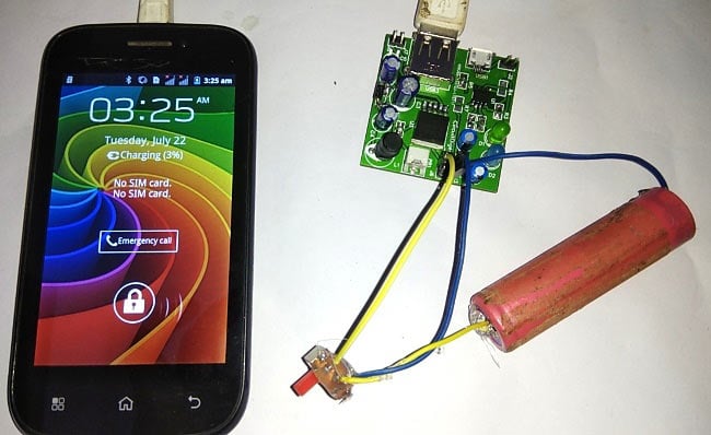
The features of the digital products are growing enormously which triggers the frequent usage of smart phones in several applications. Thus the battery backup time is getting decreased. It will be fun to build a Power Bank for Mobile Phone as spare charging source for emergency purpose which is also portable.
Previously we have made the Power bank circuit simply using Boost converter Module and TP4056A Module. But here in this project, we are creating a single PCB instead of using two different modules to charge mobile phones. Although the previous one was easy to build but this one is neat, compact and customizable.
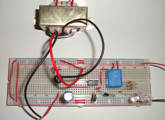
Emergency light is an integral part of household electronics nowadays. We all know Emergency light is used during the power failure to light up the home. As it is used during the power failure, it should last long, hence generally bright white LEDs are used in emergency light, because they produce more light and consume less power. Emergency light is very useful and popular project in DIY section. So today we are going to build a simple and cost effective emergency light.
In this emergency light circuit, when the Power goes OFF, the emergency light activates automatically. We have used four bright white LEDs, more LEDs can be added to produce more light considering that total current consumption should not exceed the supply current. Ultra bright white LED consumes 3v and 20mA current.